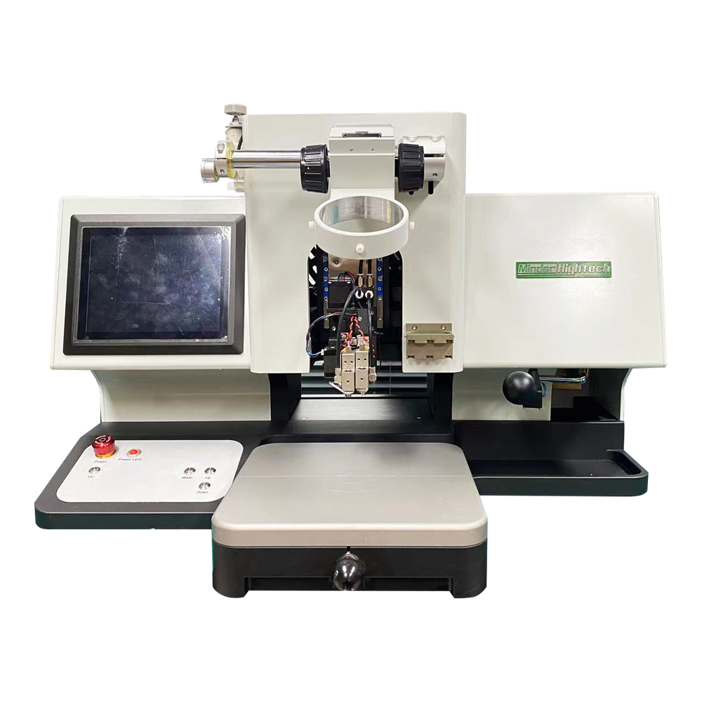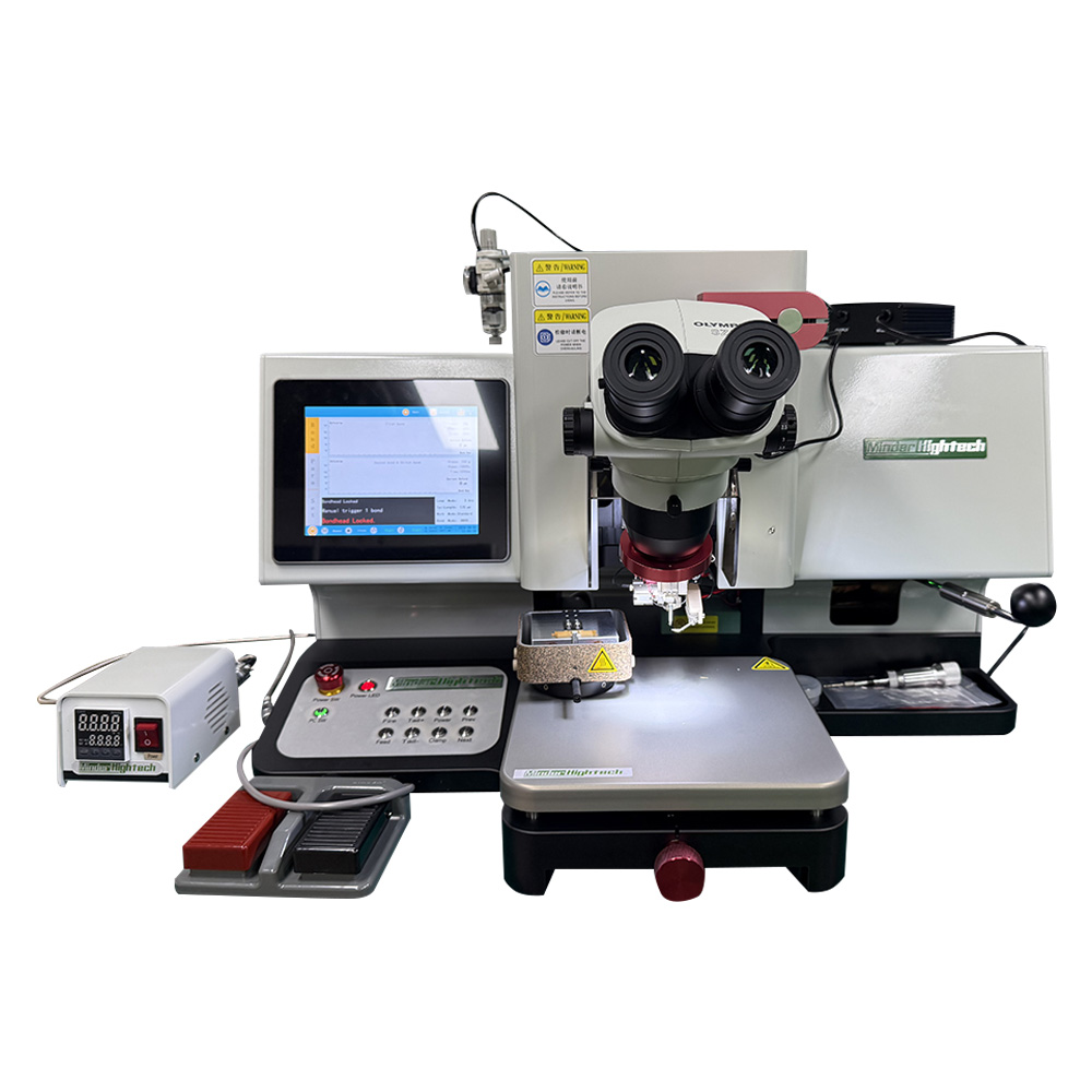
1. Equipment Application
This equipment is used for the encapsulation of solid molded tantalum series components.
2. Equipment Structure, Functions, and Controls
|
2.1 Equipment Structure, Controls, and Button Layout |
|
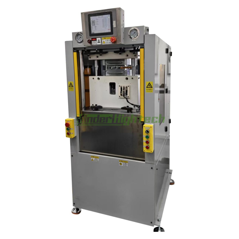
1. The equipment features a left-right structural layout: the left section houses the operational components, while the right section houses the control components. The rear of the machine is designed to accommodate an operator's workspace for mold changing, and the control cabinet is located on the right side. 2. The layout of the machine's mechanisms, component mounting positions, hydraulic hose connections, and electrical systems is logically arranged to facilitate commissioning, repair, and routine maintenance. 3. The pneumatic source connection port on the side of the machine utilizes a push-to-connect fitting compatible with Φ8 (outer diameter) compressed air tubing and air blow guns. 4. The equipment is fitted with a heavy-duty mounting mechanism for suspending the air blow gun. 5. The machine is equipped with a retractable, spring-coiled PU air hose and a high-quality, wear-resistant air blow gun, both connected via quick-release couplings. 6. The guide pillars feature a chrome-plated surface finish, and the mold platen has undergone stress-relief treatment. 7. The mounting panels for the mold clamping pressure gauge and injection pressure gauge are physically separated from the main machine chassis; they are secured via screws to ensure easy access for repair and maintenance. 8. The access panels covering the motor compartment and the electrical control cabinet feature ventilated sponge-filter grilles for air intake. 9. The electrical cabinet door and the main power switch area display markings and warning labels that comply with international electrical safety standards. 10. The equipment comes with its own dedicated status identification plate. 11. The machine features a PLC-based touchscreen interface, and the entire hydraulic control system utilizes servo control technology. 12. All electrical wiring and cables used within the equipment are oil-resistant. 13. Linear electronic scales (transducers) are employed to detect and monitor the stroke positions within the injection system. 14. The mold temperature control system utilizes Solid State Relays (SSRs) to implement PID-based constant temperature control functionality. 15. The power supplies for the hydraulic drive system and the heating system are independently controlled to prevent mutual interference during maintenance operations. 16. The hydraulic solenoid valves are designed to allow for manual mechanical override (facilitating maintenance) and feature appropriate identification markings. 17. The machine's various parameters—including stroke positions, hydraulic circuit sequences, solenoid valve states, mold clamping status, and injection system stroke positions—are clearly displayed on the front control panel. 18. The machine features a touchscreen display for settings and control functions; however, frequently used operational buttons are physically mounted on a separate control panel located directly beneath the display screen. 19. The left and right-hand control button panels shall be installed as two separate units. |
Contact: Minder Hu
Phone: 0086-15813334038
Tel: 020-84789496
Email: md@minder-hightech.com
Add: 813,No.43,Xinshuikeng Section, Shixin Road, Dalong street,Panyu District,Guangzhou. Zip:511442